Table of Contents
Hardware Setup
This lab began with some hardware changes that will be used to interface each of the robot's components in future labs. Specifically, I replaced with pre-existing connector of one of my 650 mAh batteries with a JST connector in order to connect to the Artemis board. This will allow the Artemis to run without needing to be connected to my laptop. Additionally, I soldered QWIIC connectors to each TOF sensor board.
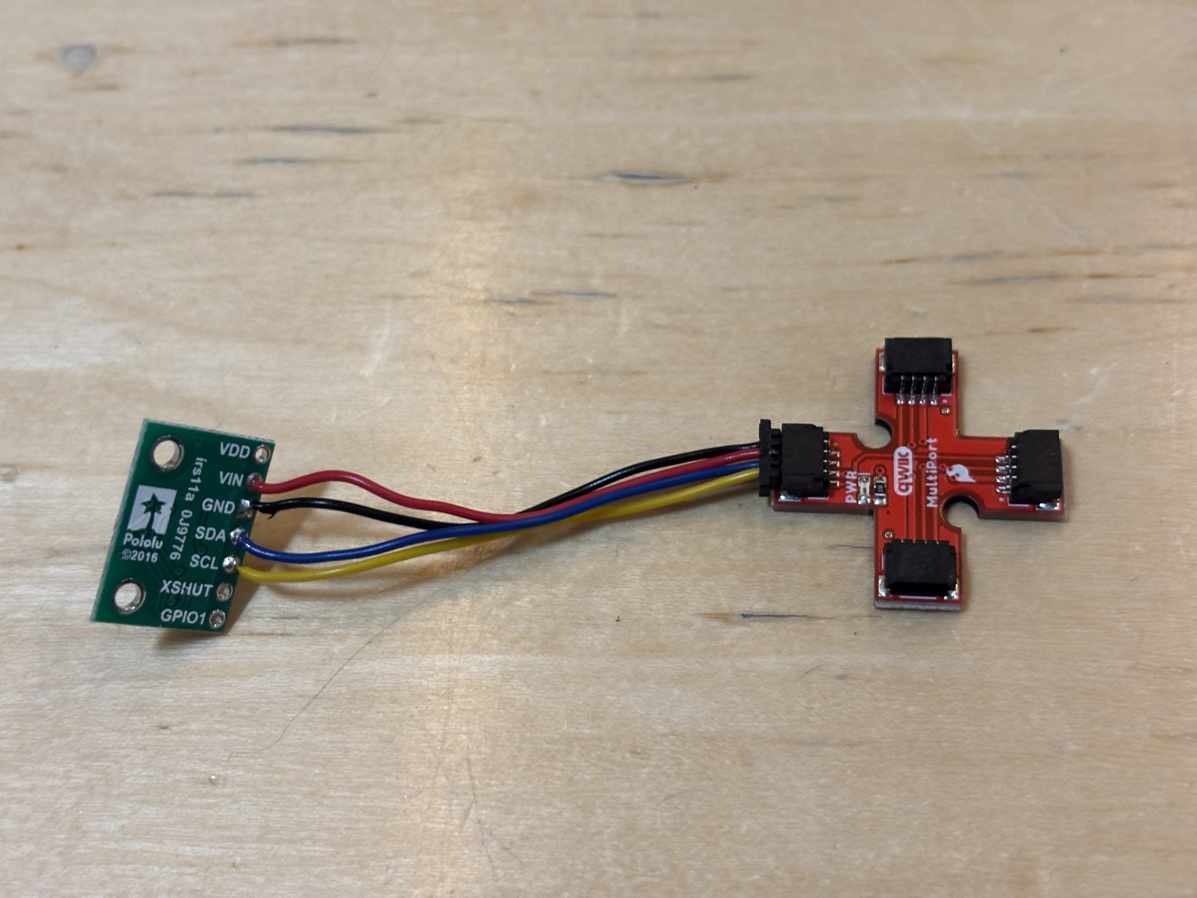
Seen below is one TOF sensor connected to the QWIIC multiport board:
With these hardware updates complete, I began my analysis of the Time of Flight (TOF) sensors that will be implemented on my robot.
Prelab
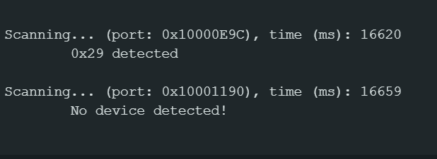
First, I examined the I2C address of the TOF sensor. According to its datasheet, the sensor's default address is 0x52. However, the sample Arduino program detected the sensor's address at 0x29. This it to be expected. I2C addresses consist of 7 bits followed by a read/write bit. When the Arduino program runs, it cycles through all possible addresses and attempts to write to each address. When the program successfully writes to an address, it records that address. 0x52 is equal to 0x29 left shifted by 1 bit. Following the TOF sensor's datasheet, if a user wants to write to the sensor, the user should transmit to an address of 0x29 followed by a 0 (indicating a write operation), which is equal to 0x52. If a user wishes to read from the TOF sensor, they should transmit an address of 0x53, indicating that they are interacting with the device as address 0x29 and wants to perform a read operation (represented as a 1 in the R/W bit).
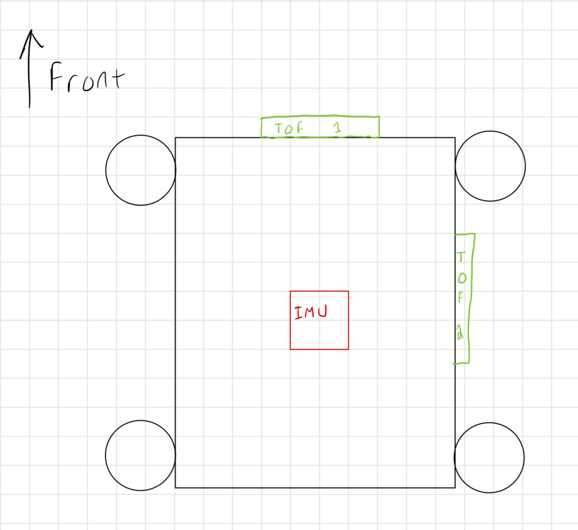
The TOF sensors will acts as the "eyes" of my robot. These sensors will be able to detect objects, such as a wall, that are in front of them. Therefore, it makes sense to implement more than one sensor. If the robot only used one TOF sensor, it would only be able to "see" in one direction and would fail to detect objects in other directions. In an ideal setup, the robot would be able to view all directions continuously, but this would require additional power and memory which my robot does not have.
I chose to place one TOF sensor on the front of my robot and the other sensor on the right side of the robot. This placement will allow the robot to see in front of it and on its side. To detect a full 360 degrees of surroundings, the robot can rotate in place to scan its environment. Depending on the tasks of future labs, I may adjust my sensor placement.
This placement causes a few blindspots. Notably, the robot is capable of moving in both forward and backwards directions. If the robot moves in reverse, it will be unable to see where it is moving. Additionally, the robot is unable to see above itself. If the robot is performing a stunt, such as a backflip, it will have only have one sensor to rely on instead of two as it rotates.
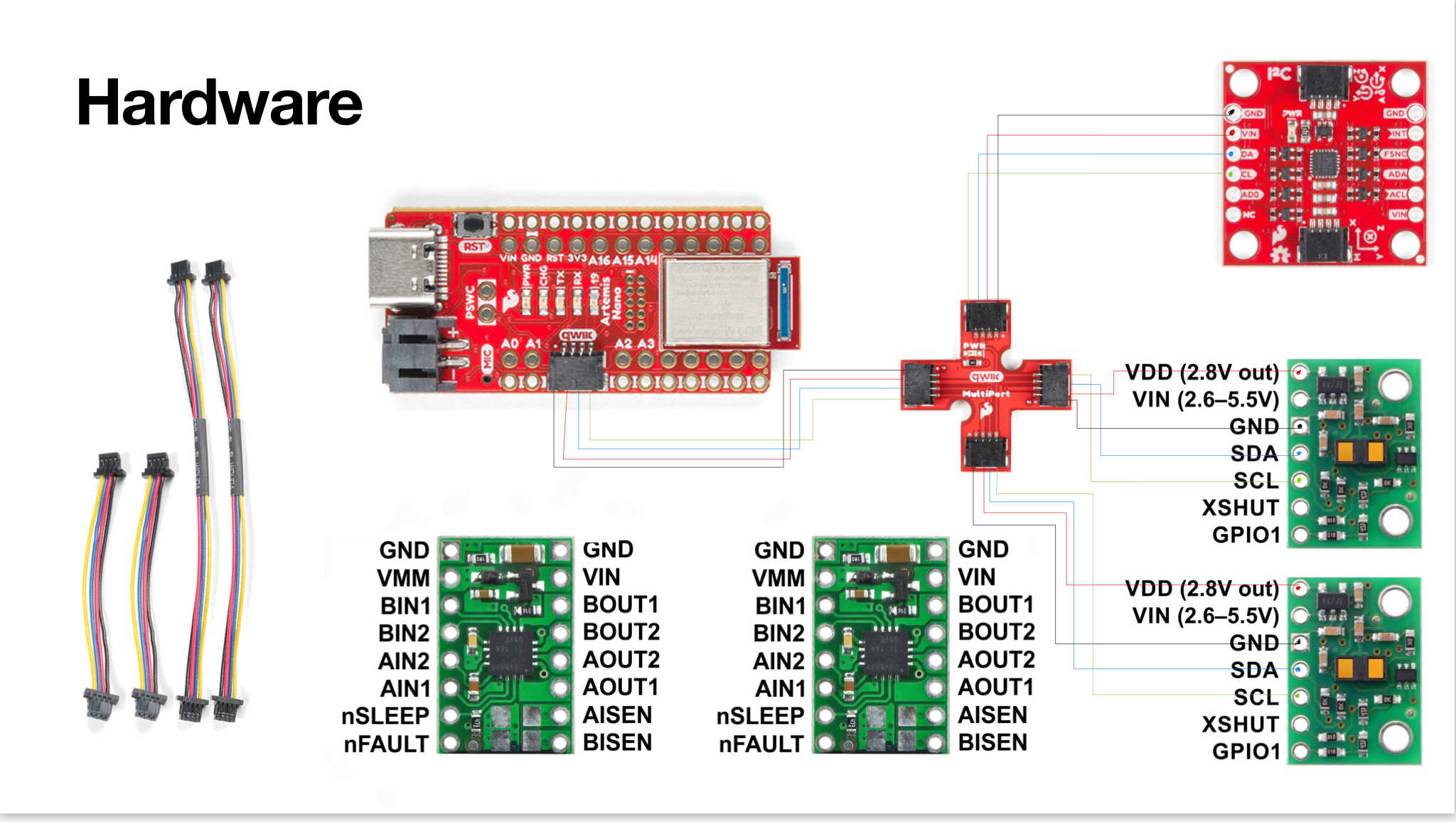
Shown below is a sketch of the wiring I used to connect each of my robot's sensors to the Artemis board. Red wires indicate Power (VDD), Black wires are Ground (GND), Blue wires are Serial Data (SDA), and Green wires are Serial Clock (SCLK). Although the physical connectors use yellow wires for the clock connection, yellow is difficult to see when drawn on a white background, hence why I used green to represent these wires. Each sensor is connected using QWIIC connectors to a multiport board which is then connected to the Artemis.
TOF Sensor Testing and Analysis
One TOF Sensor
The specific TOF sensor used for this lab has three distance modes. Each mode performs best at different ranges. For example, the short distance mode performs best within a range of 136 centimeters. The long distance mode performs best up to a range of 360 centimeters but is more heavily impacted by ambient light. Since the robot needs to be able to react quickly to sudden changes in its environment, such as stopping just before crashing into a wall, I chose the short distance mode for both of my sensors. The short distance mode allows the Artemis to record distance measurements faster than other TOF sensor modes. Depending on future lab tasks, I may adjust each sensor's mode.
I started by testing the accuracy of the short distance range mode of my TOF sensor. To do this, I positioned the sensor at several distances from a wall in increments of three inches using a tape measure to record the actual distance. For each distance, I collected 100 sensor measurements and plotted the sensor's mean recorded distance. For each distance trial, I also recorded the sensor's mean ranging time. I repeated this test three times to check for repeatability and consistency with the sensor's measurements.
Plotted below is the mean value of the sensor's measured distance over three trials versus the actual distance between the sensor and a wall. The sensor is quite accurate over its maximum range, and even measures the distance fairly well when slightly outside of this range. For example, at 57 inches (144.78 cm), the error is small despite this distance being outside of the short mode range. However, once the sensor exceeds 60 inches (152.4 cm), the error becomes significant.
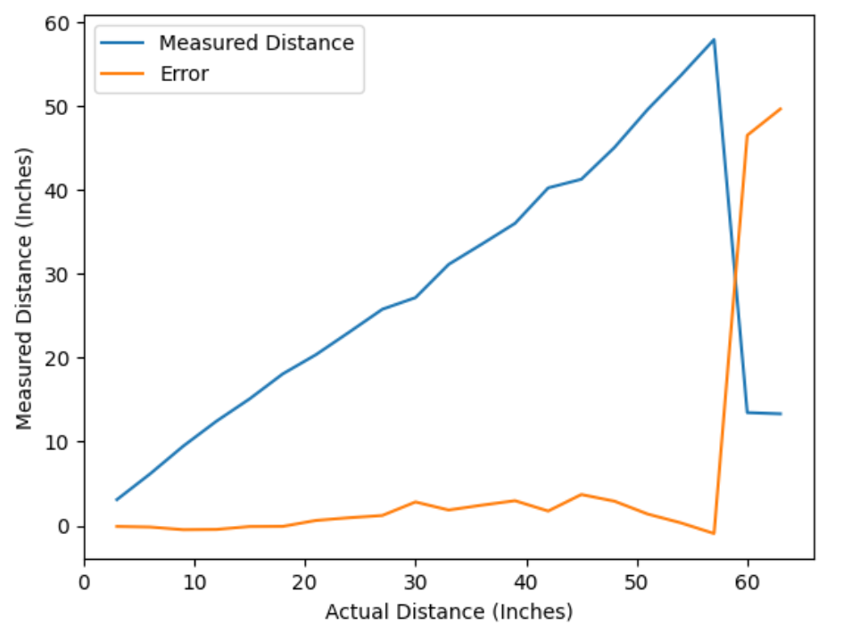
The mean ranging time for each trial was between 49 and 51 milliseconds. The sensor's datasheet states that the minimum ranging time using short distance mode is 20 ms, so this mean time is quite good compared to the sensor's maximum performance.
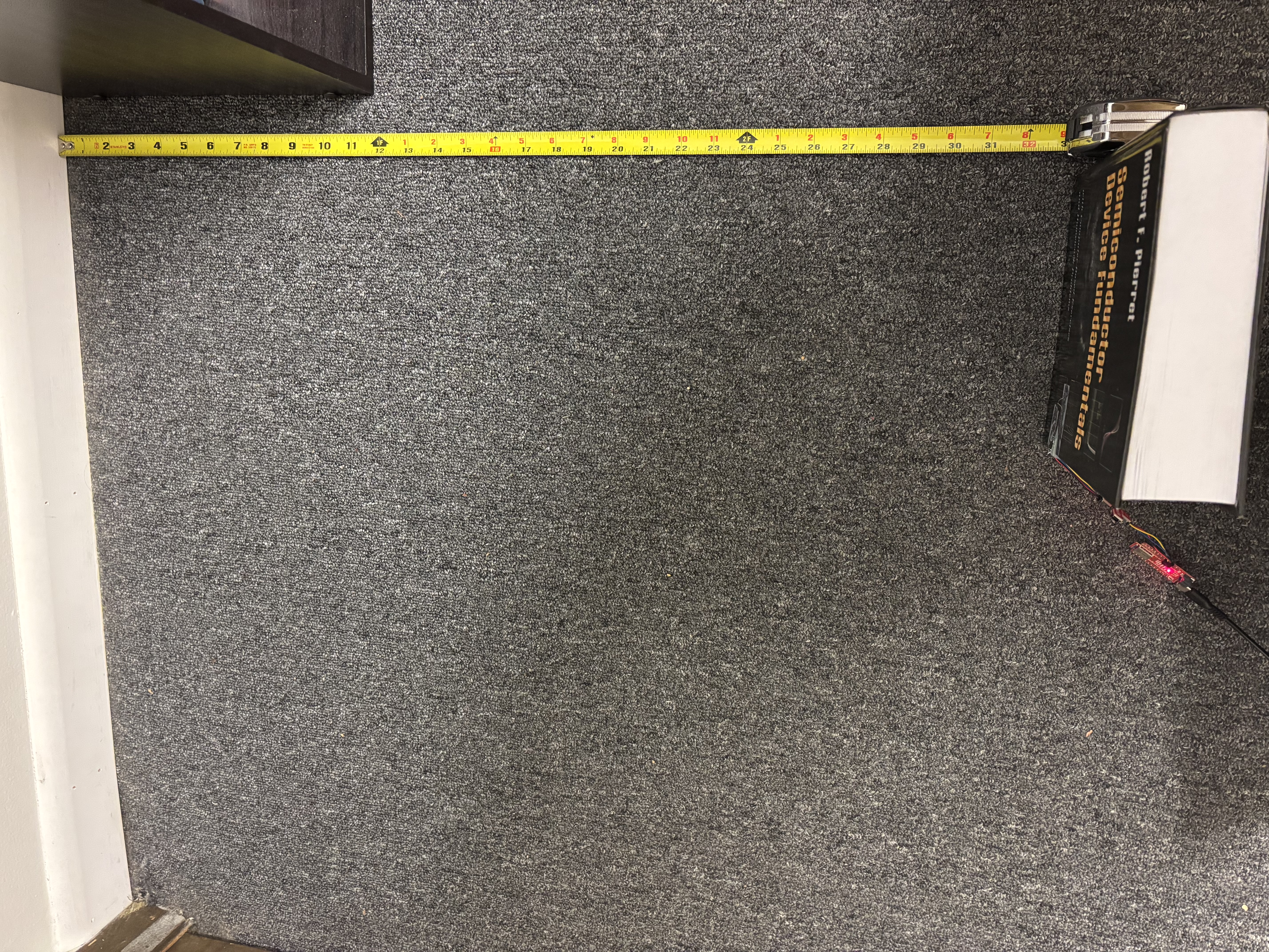
Pictured below is a photograph of my test setup. I taped the TOF sensor to a textbook to act as a constant vertical surface. I used a tape measure to measure the distance between the sensor and the wall.
Interfacing Two TOF Sensors
Next, I interfaced both TOF sensors to work simultaneously. There are two methods to do this. One method requires constantly switching a sensor on and off, while the other simply changes the I2C address of the second sensor. I decided to go with the second option as I'd rather only have to run additional code during the sensor initialization rather than each time I want to measure a sensor's data.
It was not until Tuesday night that I realized I needed an additional wire for this (I should've read the lab handout more closely). Since I do not own a soldering iron, I had to get creative for this test. I plan to solder a permanent wire when I am in the physical lab space.
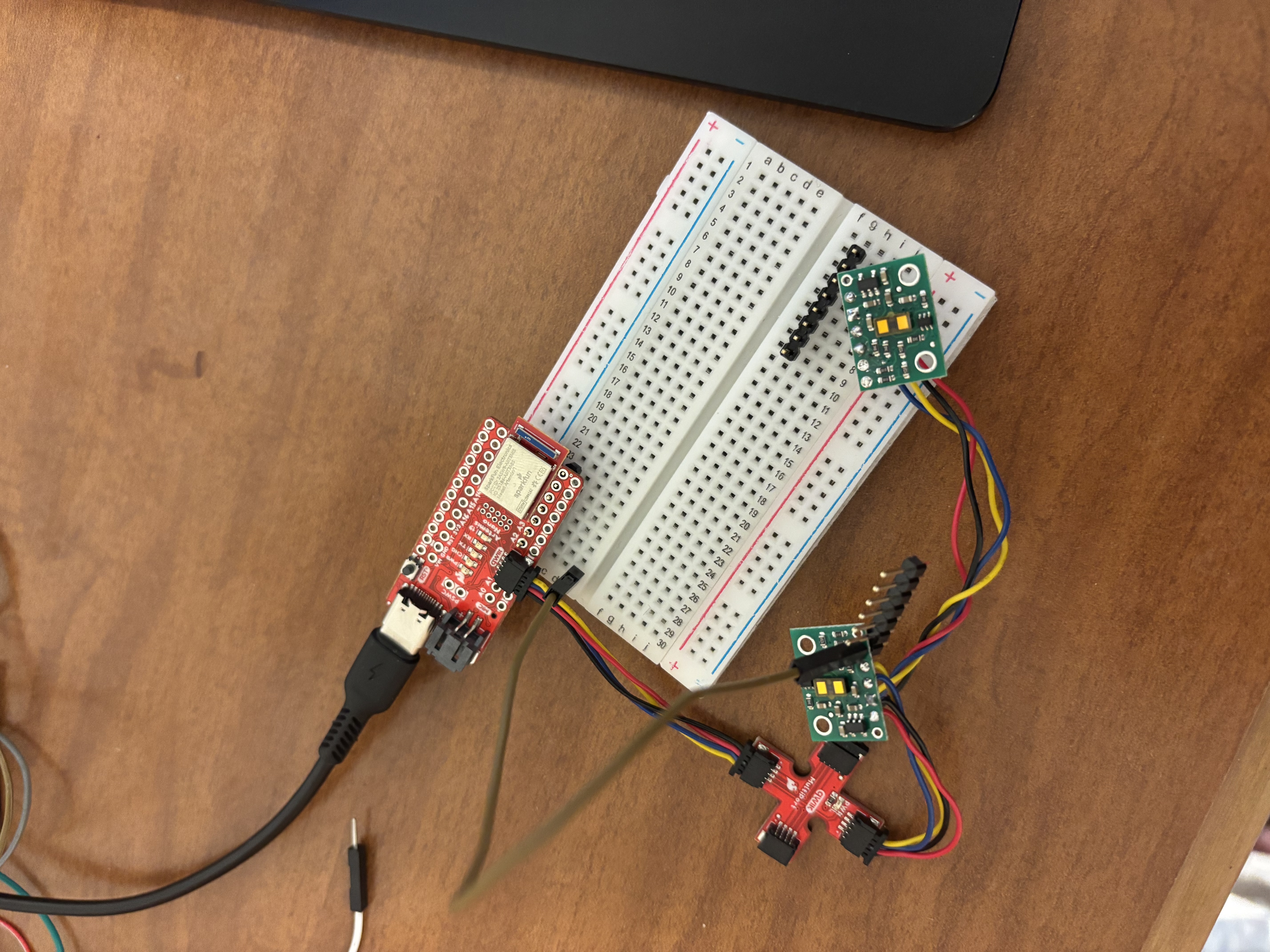
Luckily, I had a breadboard and some jumper wires at my apartment, so I was able to create a temporary setup to establish the necessary SHUTDOWN wire connection, as seen below:
Using the following initialization code, I was able to successfully change the I2C address of one of the TOF sensors, allowing for both sensors to measure distance data at the same time.
#define SHUTDOWN_PIN 2
#define LOW 0
#define HIGH 1

SFEVL53L1X distanceSensor1;
SFEVL53L1X distanceSensor2(Wire, SHUTDOWN_PIN);


void setup() {
  Wire.begin();

  Serial.begin(9600);
  Serial.println("VL53L1X Qwiic Test");

  pinMode(SHUTDOWN_PIN, HIGH);
  distanceSensor2.sensorOff();

  distanceSensor1.setI2CAddress(0x56);
  pinMode(SHUTDOWN_PIN, LOW);

  if (distanceSensor1.begin() != 0) //Begin returns 0 on a good init
  {
    Serial.println("Sensor 1 failed to begin. Please check wiring. Freezing...");
    while (1);
  }

  if (distanceSensor2.begin() != 0) //Begin returns 0 on a good init
  {
    Serial.println("Sensor 2 failed to begin. Please check wiring. Freezing...");
    while (1);
  }
  Serial.println("Sensors online!");
  distanceSensor1.setDistanceModeShort();
  distanceSensor2.setDistanceModeShort();
}
In the video below, I demonstrate that both sensors are able to record data simultaneously and respond to unique changes in their environment.
Fast TOF Code Execution
Now that I had both TOF sensors working simultaneously, it was time to speed up the execution time of my code. Instead of waiting for each sensor's data to be ready before printing, I only recorded sensor data IF the sensor was ready. If the sensor was not ready, I simply skipped over the measurement recording code and continued executing my loop.
Using the following loop code, I was able to record sensor data only when it was ready, allowing the Artemis to continue operating instead of waiting for each sensor to be available.
void loop(){
  float start_time = millis();
  distanceSensor1.startRanging();
  distanceSensor2.startRanging();

  if(distanceSensor1.checkForDataReady()){
    float distance1 = distanceSensor1.getDistance();
    distanceSensor1.clearInterrupt();
    distanceSensor1.stopRanging();
    Serial.print("Distance1(mm): ");
    Serial.println(distance1);
  }
  if(distanceSensor2.checkForDataReady()){
    float distance2 = distanceSensor2.getDistance();
    distanceSensor2.clearInterrupt();
    distanceSensor2.stopRanging();
    Serial.print("Distance2(mm): ");
    Serial.println(distance2);
  }
  float end_time = millis();
  Serial.print("Clock Period: ");
  Serial.println(end_time - start_time);
}
As seen below, the sensor data is only available once every 10 loop cycles. By allowing the Artemis to continue operating when sensor data is unavailable, the robot can perform other tasks while waiting for new sensor data. It is clear that the Artemis can operate much faster than the TOF sensors can record data. It takes each sensor roughly 50 ms to record data which is quite slow compared to other operations occuring on the Artemis.
Distance1(mm): 215.00
Distance2(mm): 28.00
Clock Period: 53.00
Clock Period: 6.00
Clock Period: 6.00
Clock Period: 6.00
Clock Period: 6.00
Clock Period: 6.00
Clock Period: 7.00
Clock Period: 7.00
Clock Period: 7.00
Clock Period: 6.00
Clock Period: 6.00
Distance1(mm): 135.00
Distance2(mm): 28.00
Bluetooth Connection
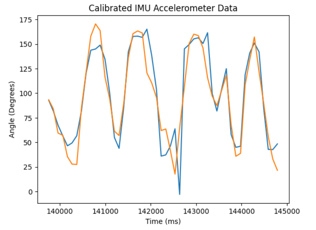
Lastly, I implemented a function that allowed for TOF sensor data to be recorded via Bluetooth. This function also records IMU roll and pitch data (see Lab 2). Initially, I had this function use the complementary filter IMU recording routine, but due to the slow recording time of the TOF sensors, this filter (mainly due to the gyroscope) was quite inaccurate. Instead, I used calibrated data recorded by the IMU's accelerometer for this measurement. For future labs, if recording IMU data via the complementary filter is needed, it should be done independently from the TOF sensors.
int start_time = (int)millis();
int index = 0;
float lastTime = millis();
time_stamps[0] = millis();
gyro_roll[0] = 0;
gyro_pitch[0] = 0;
// Record Time Data Rapidly
while((int)millis() < start_time + RECORD_TIME && index < TIME_ARRAY_SIZE){
  while(!myICM.dataReady());
  myICM.getAGMT(); // Collect data for RECORD_TIME ms
  time_stamps[index] = (int)millis();
  roll_stamps[index] = correctedRollDeg(&myICM);
  pitch_stamps[index] =  correctedPitchDeg(&myICM);

  distanceSensor1.startRanging();
  while (!distanceSensor1.checkForDataReady());
  tof1_stamps[index] = distanceSensor1.getDistance();
  distanceSensor1.clearInterrupt();
  distanceSensor1.stopRanging();

  distanceSensor2.startRanging();
  while (!distanceSensor2.checkForDataReady());
  tof2_stamps[index] = distanceSensor2.getDistance();
  distanceSensor2.clearInterrupt();
  distanceSensor2.stopRanging();
  index++;
}
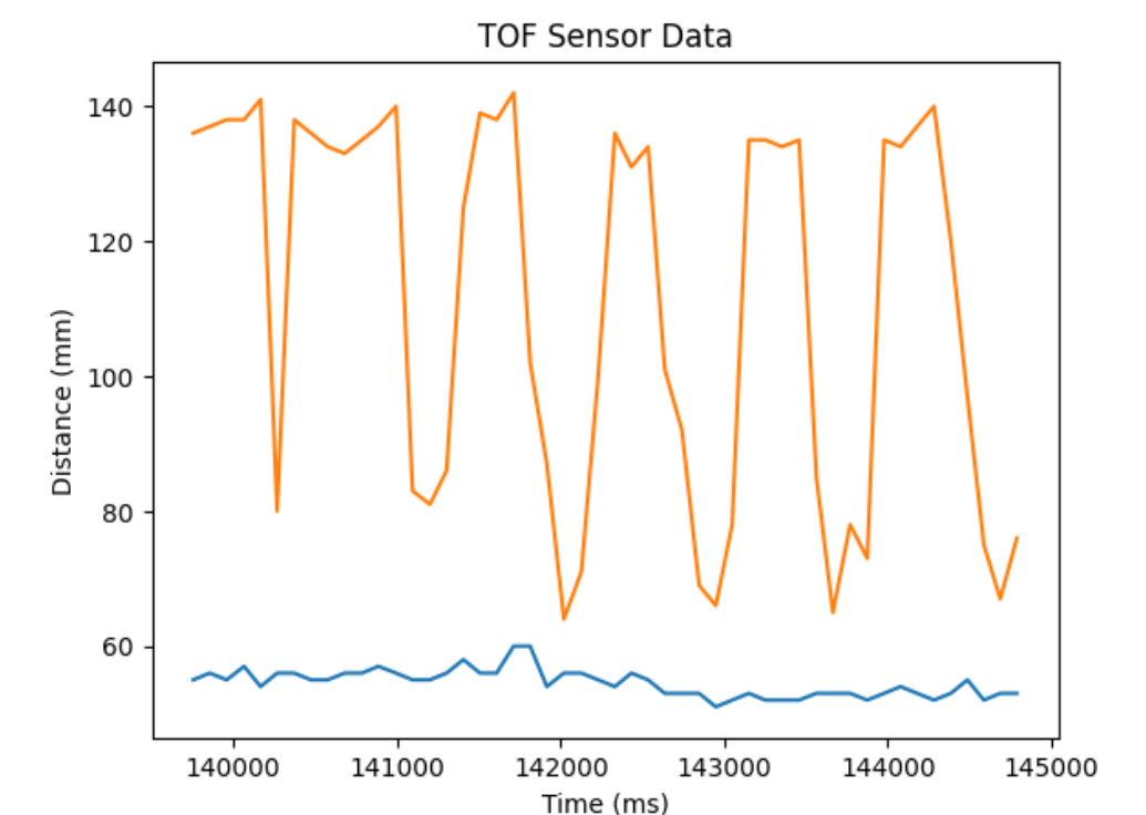
After recording data for 5 seconds, I plotted the following graphs. As explained above, each TOF sensor has a recording time of roughly 50 ms. With two sensors, this time doubles to 100 ms. Thus, data is only recorded every 100 ms, even though each TOF sensor can record at twice this speed, and the IMU can record much faster than this.
This lab focused on implementing "vision" onto my robot. By using TOF sensors, my robot is now capable of measuring distances between various objects and itself. I am excited to use both the TOF and IMU sensors to execute more complex robotics tasks in future labs.
Acknowledgement: I watched several YouTube videos and browsed robot-electronics.co.uk to better understand I2C addressing. I referenced Wenyi Fu's Lab 3 webpage to better understand how to change the TOF sensor's I2C address.