Table of Contents
Wiring Diagram and Battery Discussion
This lab focused on integrating two DRV8833 motor controllers onto the robot. In addition, one of the tasks of this lab was to integrate each electronic component from previous labs onto the physical robot. This includes the IMU, two TOF sensors, two batteries, and the Artemis MCU board.
Pictured below is a wiring diagram that shows how each component will be connected:
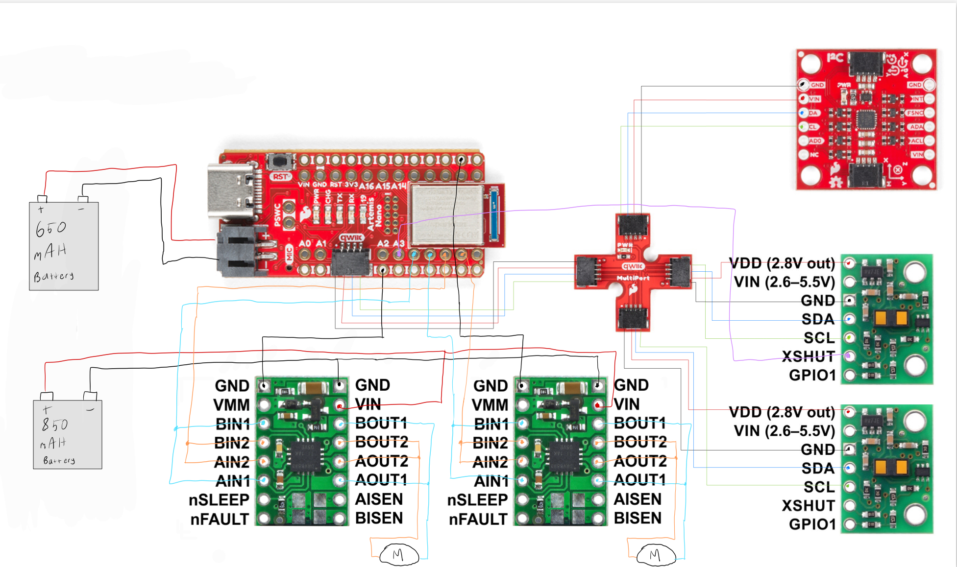
As explained in lab 3, the two TOF sensors and the IMU are connected to the Artemis using QWIIC connectors. The motor controllers are connected to the Artemis solely by soldering wires to each board. I used an 850 mAh battery with a nominal voltage of 3.7V to power both motor controllers. Each motor controller also has a GROUND connection to the Artemis to help mitigate some EMI issues. Each motor controller is connected to two Artemis pins that are capable of outputting analog voltages via PWM. I used pins A4-A7 for these input signals. Likewise, each controller is connected to one motor on the robot, which drives two wheels. The Artemis is also powered by its own 650 mAh battery.
Testing a Single Motor Controller
To start, I soldered the necessary wires to one motor controller and the Artemis. Then, I began testing this controller to ensure that it functioned properly before moving on to the next motor controller. I used a digital multimeter to check for any unexpected solder shorts as well as to ensure that each connection was secure. For testing, I powered the Artemis using a USB cable to my laptop, and I powered the motor controller using a power supply. I used a voltage of 3.7V with the power supply to mimic the 850 mAh battery's nominal voltage. The DRV8833's datasheet indicates that the controller can be supplied with any voltage between 2.7V and 10.8V.
I used the following code to test the output of the motor controller. I connected an oscilloscope to the two output wires of the controller and measured the output voltage. I used the following code to conduct this test:
#define PIN_POS 4
#define PIN_NEG 6

void loop(){
  analogWrite(PIN_NEG, 0 );
  for( int i = 0; i < 255; i = i + 1 ){
    analogWrite(PIN_POS, i );
  }
}
The results can be seen in the following video:
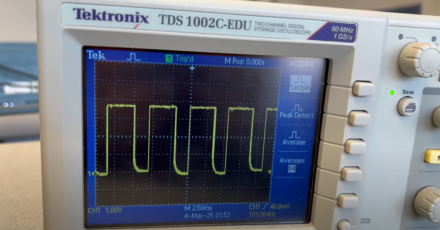
As seen on the oscilloscope, the motor controller is capable of being controlled by the Artemis. By changing the analog voltage sent via PWM from the Artemis, the motor controller is able to control the speed of the motor it is connected to.
Now that I was sure that the motor controller was working correctly, I connected its outputs to a set of wheels on my robot. I used the following code to spin the wheels in both directions, with the direction alternating every three seconds:
#define PIN_POS 4
#define PIN_NEG 6

void loop(){
  analogWrite(PIN_NEG, 0 );
  analogWrite(PIN_POS, 127);
  delay(3000);
  analogWrite(PIN_NEG, 127 );
  analogWrite(PIN_POS, 0);
  delay(3000);
}
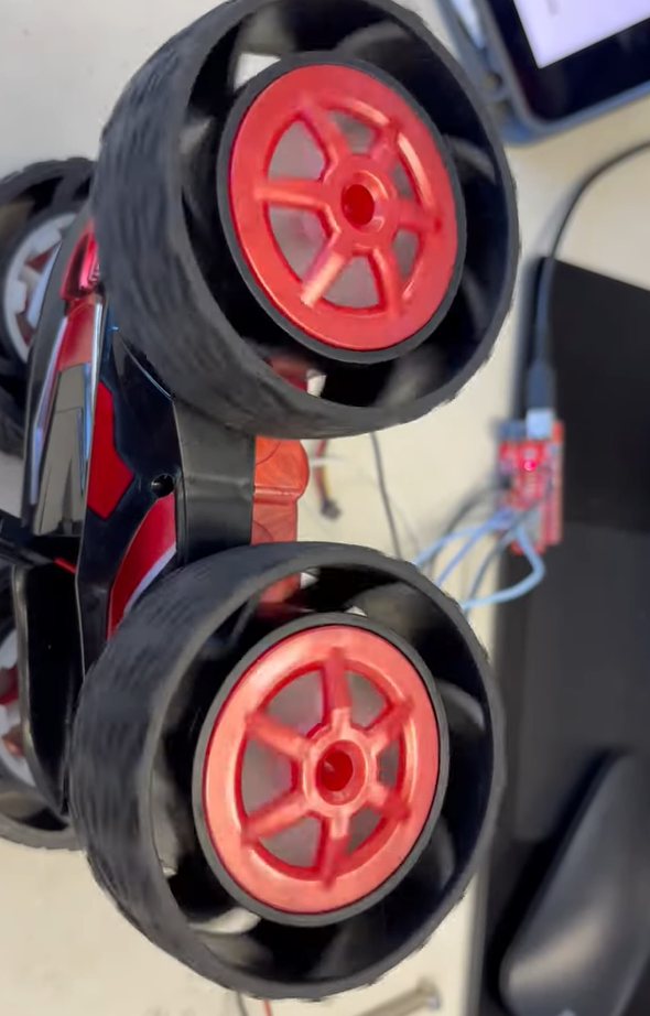
The results are shown here:
Now that one motor controller was properly connected to the robot and working correctly, I repeated the same process with the second motor controller. This included testing with the oscilloscope as well as connecting it to the robot's wheels to ensure that the controller worked. The results of having both sets of wheels controlled by the motor controllers will be demonstrated throughout the remaining videos of this lab.
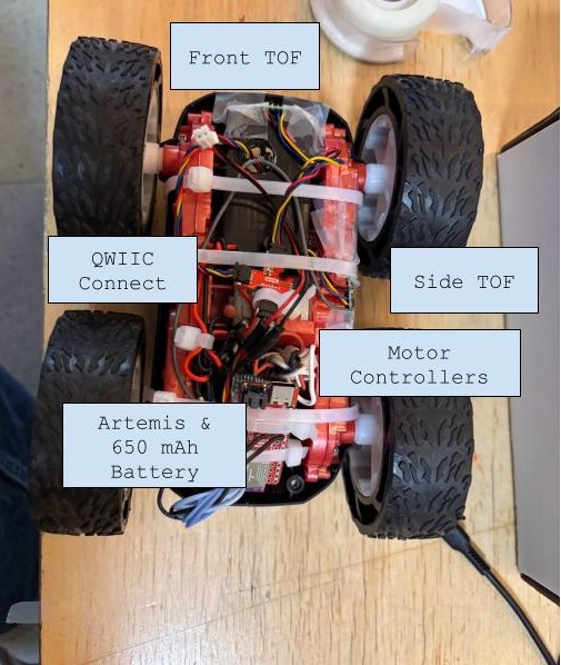
Electronics Integration
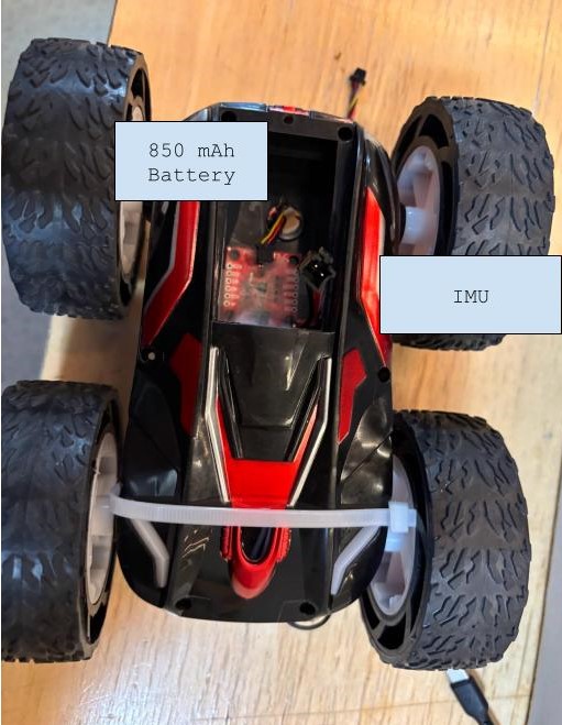
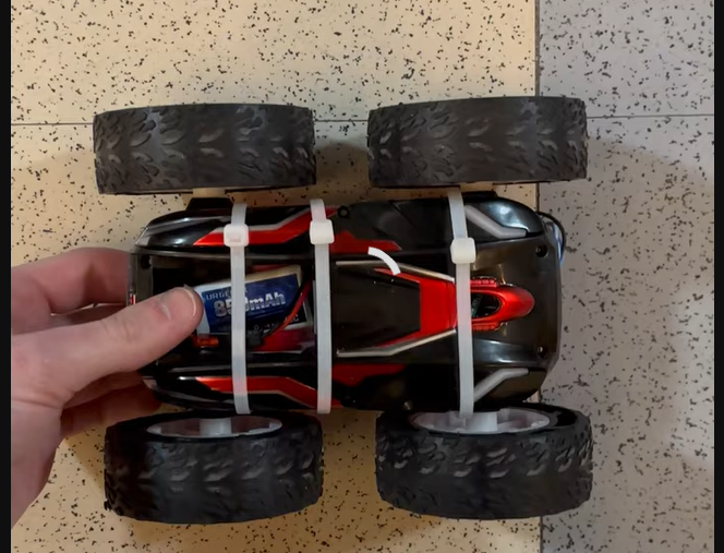
With both motor controllers connected and working, it was time to tidy things up within the robot. I attached the two motor controllers, the Artemis, and the 650 mAh battery in the back compartment of the robot. I attached one TOF sensor to the side of the robot and the other TOF sensor to the front. I attached the IMU in a horizontal position in the front compartment of the robot.
PWM Limits
When the robot is tilted on its side or lifted in the air, the wheels can turn given nearly any PWM voltage. However, when the robot is on the ground, factors such as static friction can inhibit the wheels from turning, despite being controlled with a nonzero input voltage. I tested several PWM values to determine the minimum voltage needed for the robot to move in a straight line and execute a turn. In PWM increments of five, I determined the minimum value needed for the robot to move in a straight line was 40 (duty cycle of 0.156). For turning, I measured a minimum value of 90 (duty cycle of 0.353). For each case, when the PWM value was below the measured threshold, the robot did not move. This test was conducted with the 850 mAh close to but not exactly at full charge. I used the following code to conduct this test:
#define PIN_RIGHT_NEG 4
#define PIN_LEFT_NEG 7
#define PIN_RIGHT_POS 6
#define PIN_LEFT_POS 5

for(int i = 0; i < 51; i++){
  analogWrite(PIN_RIGHT_NEG,0);
  analogWrite(PIN_LEFT_NEG,0);
  analogWrite(PIN_RIGHT_POS,5*i);
  analogWrite(PIN_LEFT_POS,50*i);
  delay(2000);
  analogWrite(PIN_RIGHT_POS,0);
  analogWrite(PIN_LEFT_POS,0);
  delay(2000);
}
This code increments the PWM value by 5 (within a range from 0 to 255) every two seconds. In between each increment, I turn each motor off in order to detect when there is a transition between PWM values.
Calibration
In theory, the two motors should be identical to each other. However, due to manufacturing differences and other physical effects, the motors do not spin at exactly the same rate. To adjust for this, I implemented a calibration factor onto one of the motors. This resulted in the two motors spinning at nearly the same rate, allowing the robot to move in a straight line.
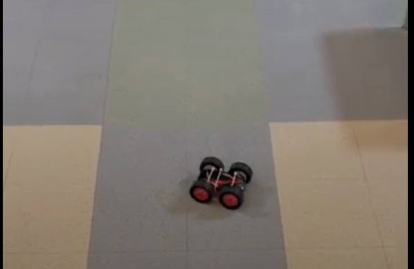
With no calibration factor, the robot was capable of moving in a relatively straight line for over six feet, as seen in the video below:
Through testing different values, I determined the optimal calibration factor to be 1.04. The left motor spins slightly faster than the right motor on my robot. To account for this, I set the PWM value for the right motor to be 1.04 times the PWM value applied to the left motor. While not perfect, this allowed the robot to move in a straighter line than with zero calibration. I expect further control methods such as PID control will improve this imperfection even more.
With the added calibration factor, the robot is able to move in a straight line for over six feet:
In each video, I align the wheels of the robot with a floor tile. Each tile is one foot long. As seen in the calibrated motion video, the wheels stay along the edge of the tile for nearly the entire motion, indicating that the robot moves in a straight line.
Open Loop Control
Finally, I implemented some basic open loop control that made the robot move forward and execute turns. This movement is not very precise or predictable, but this will be improved upon in future labs. I used the following code to implement basic motion on the robot. This code continuously loops, resulting the robot moving forward for one second, turning right, and then repeating.
void loop() {
    // Forward Motion
    analogWrite(4,0);
    analogWrite(7,0);
    analogWrite(6,50);
    analogWrite(5,1.04*50);
    delay(2000);
    // Turn
    analogWrite(4,0);
    analogWrite(7,100);
    analogWrite(6,1.04*100);
    analogWrite(5,0);
    delay(1500);
}
The results can be seen in the following video:
Overall, this lab culminated in having a fully assembled robot that was capable of basic motion. Now that the hardware of the robot has been completed, future labs will focus on more sophisticated robot control methods.
Acknowledgement
I consulted Nila Narayan's Lab 4 webpage to develop a conceptual understanding of the lab and its required tasks.