Table of Contents
Prelab
To begin, I implemented several bluetooth commands that would assist with debugging and recording data from the robot. This involved creating arrays on the Artemis that store different data readings (TOF distance, motor speed, etc.) with respect to time.
Each iteration of my PID control loop, I call the function record_data() to store current sensor readings into their corresponding arrays.
void record_data(
  int C_TIME,
  float C_DISTANCE,
  float C_L_SPEED,
  float C_R_SPEED,
  float C_KP,
  float C_KI,
  float C_KD
){
  if(INDEX < 2000){
    time_stamps[INDEX] = C_TIME;
    tof1_stamps[INDEX] = C_DISTANCE;
    left_motor_speeds[INDEX] = C_L_SPEED;
    right_motor_speeds[INDEX] = C_R_SPEED;
    KP_ARRAY[INDEX] = C_KP;
    KI_ARRAY[INDEX] = C_KI;
    KD_ARRAY[INDEX] = C_KD;
    INDEX += 1;
  }
}
When the PID control loop has finished executing after ten seconds, I can send this data to my laptop using the following bluetooth command:
case SEND_PID_DATA:{
    Serial.println("Sending Data!");
    for(int i = 0; i < TIME_ARRAY_SIZE; i++){
        tx_estring_value.clear();
        tx_estring_value.append(time_stamps[i]);
        tx_estring_value.append("|");
        tx_estring_value.append(tof1_stamps[i]);
        tx_estring_value.append("|");
        tx_estring_value.append(left_motor_speeds[i]);
        tx_estring_value.append("|");
        tx_estring_value.append(right_motor_speeds[i]);
        tx_estring_value.append("|");
        tx_estring_value.append(KP_ARRAY[i]);
        tx_estring_value.append("|");
        tx_estring_value.append(KI_ARRAY[i]);
        tx_estring_value.append("|");
        tx_estring_value.append(KD_ARRAY[i]);
        tx_estring_value.append("|");
        tx_estring_value.append("A");
        tx_characteristic_string.writeValue(tx_estring_value.c_str());
    }
    INDEX = 0;
    break;
}
On the Python side, my notification handler processes the received string and divides the data into discrete lists.
def notification_handler(uuid, value):
    global i
    raw_value = ble.bytearray_to_string(value)
    if raw_value[-1] == 'A':
        PID_DATA = raw_value.split("|")
        time_list.append(float(PID_DATA[0]))
        tof1_list.append(float(PID_DATA[1]))
        left_motor_list.append(float(PID_DATA[2]))
        right_motor_list.append(float(PID_DATA[3]))
        kp_list.append(float(PID_DATA[4]))
        ki_list.append(float(PID_DATA[5]))
        kd_list.append(float(PID_DATA[6]))
Additionally, I implemented several bluetooth commands to remotely control the PID constants, motor speed, and setpoint distance. One example, which sets the PID constants, is shown below:
case SET_PID_CONSTANTS:{
    success = robot_cmd.get_next_value(val_a);
    if (!success)
        return;

    success = robot_cmd.get_next_value(val_b);
    if (!success)
        return;

    success = robot_cmd.get_next_value(val_c);
    if (!success)
        return;
    PIDPOS_KP_CONSTANT = val_a;
    PIDPOS_KI_CONSTANT = val_b;
    PIDPOS_KD_CONSTANT = val_c;
}
Time of Flight Sampling Speed
Additionally, I investigated the sampling speed of my time of flight (TOF) sensor prior to creating my PID loop. I also changed the operating mode of my sensor from SHORT to LONG so that I could accurately record further distances. While this resulted in a slower sampling speed, this was not very significant when compared to the performance gain of a larger measurement distance. I set the sensor's timing budget to 33 ms and the intermeasurement period to 33 seconds. To conduct this test, I implemented a bluetooth command that loops for five seconds. Each loop iteration, the process checks if TOF sensor data is available and records this status to an array. When analyzing this data, I produced the following graphs:

Each stem indicates when data was ready from the sensor. Taking the mean time between each data point resulted in a value of 32.667 ms, or a frequency of 30.61 Hz.
PID Control - P Controller
With these tests and debugging steps out of the way, it was time to begin designing my PID controller. A PID Controlller is programmed with a value known as the setpoint. For this lab, this setpoint represents the distance between the front of the robot and a wall. Each time the PID control loop measures new data, it calculates the difference between the measured data and the setpoint. The controller then takes the value of this error, along with its integral and derivative, multiplies these values by their corresponding gains, and sums the three outputs. The controller sends this value to an acutator, such as the motors on the robot, to act in a direction that will work to reduce the measured error.
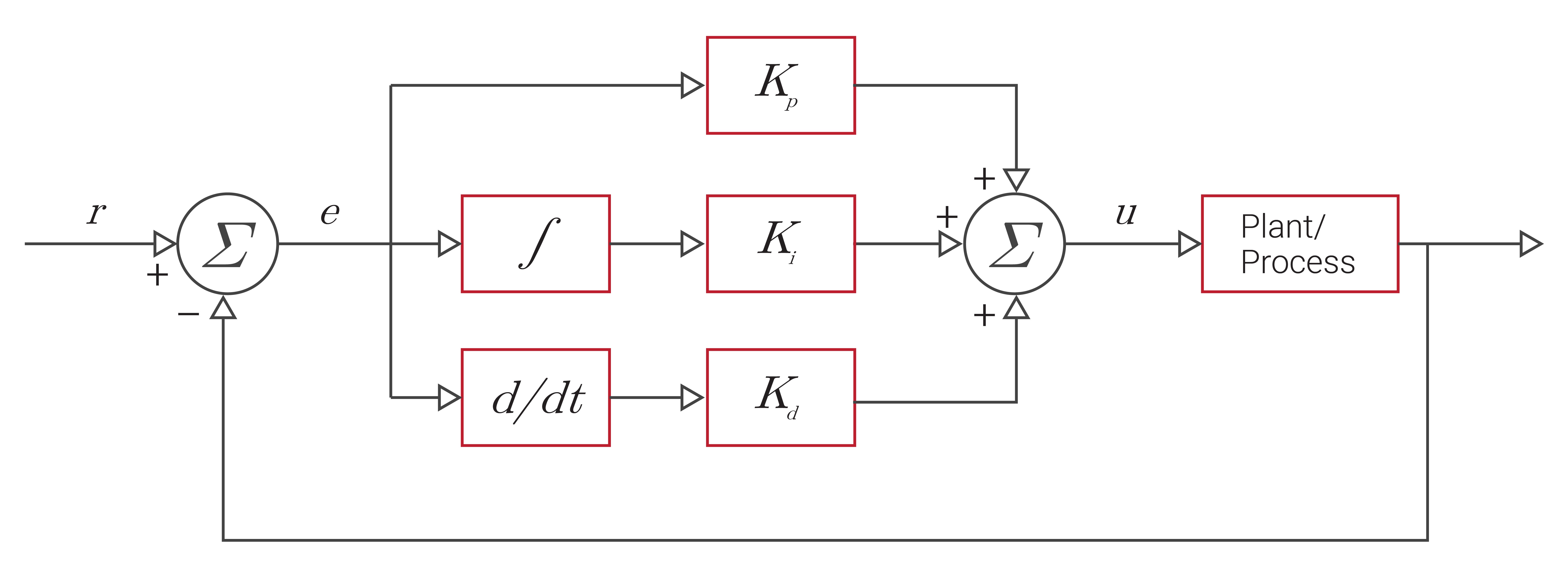
To begin, I implemented a controller that only used the proportional term, which is the measured error multiplied by a specific gain (Kp). One must be careful when setting the desired gain for the proportional term, as large gains can cause oscillations in the controller's response, and could potentially create an unstable system. A proportional gain will act directly upon the measured output, but by neglecting the Integral and Derivative terms, this controller will likely have a sizeable steady state error.
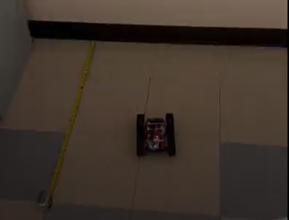
With a desired setpoint of 1 ft (304 mm), I used a controller with a gain of KP = 0.02. This controller was able to successfully control the robot's location to the setpoint. However, the robot did overshoot the setpoint by a small distance. I ran multiple tests and ultimately determined that a KP constant of 0.02 worked best for my robot. Larger values caused the robot to overshoot the setpoint and crash into the wall.
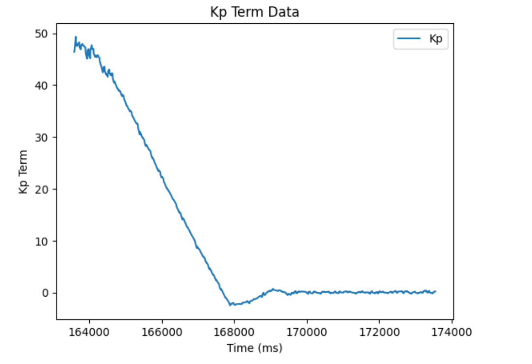
Shown below is a video of this test. The robot ends at a position of roughly 1 foot (1 floor tile) from the wall. Additionally, I recorded the output of the controller, the TOF sensor data, and the motor speeds for this test and plotted this data below.

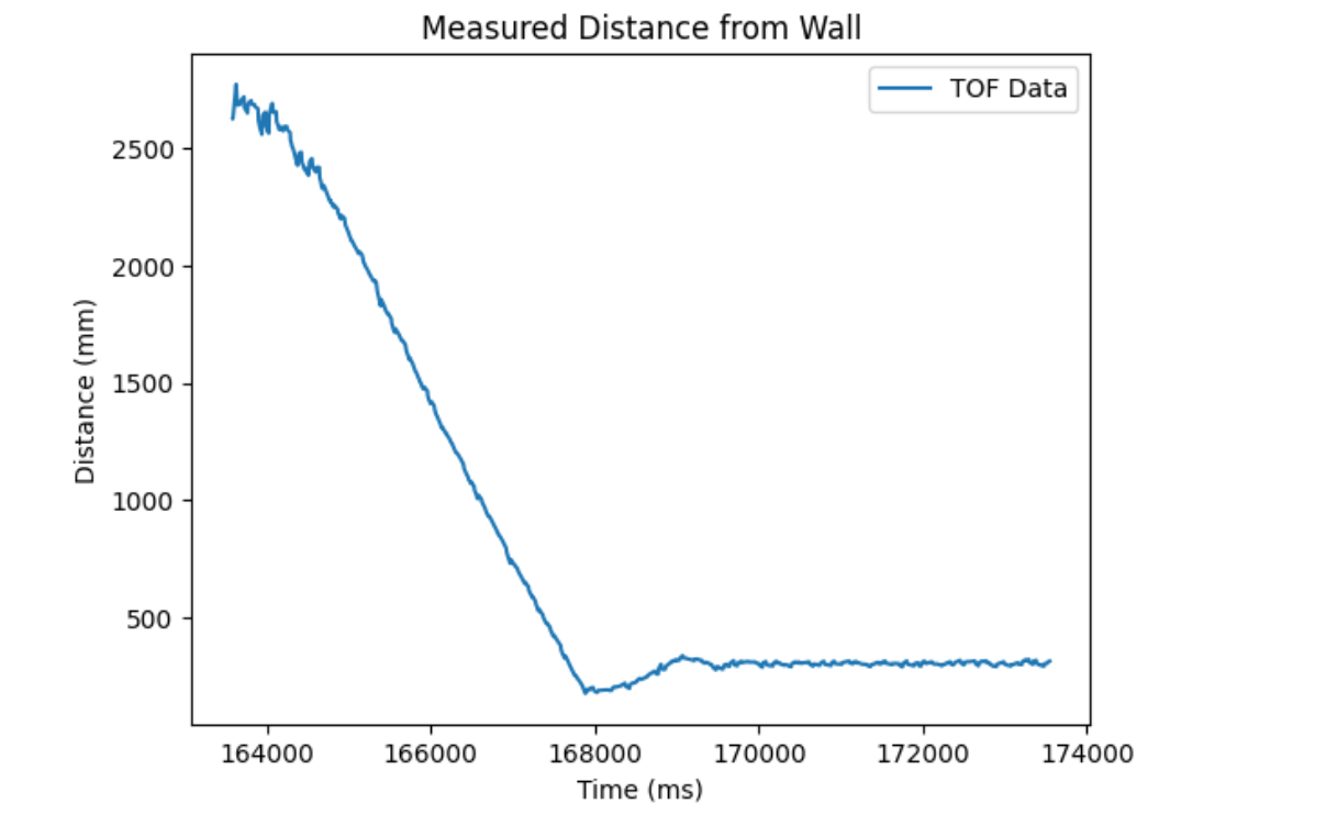
This test was done with distance extrapolation implemented on the distance sensor measurements. This procedure is explained in the following section. Additionally, I limited my motor speeds to integer values between 0 and 100, as I multiply the speed my 2.55 to produce a valid PWM write value (between 0 and 255).
My P control loop consisted of four stages, as seen below. First, the robot records new data (or uses old data if the sensor isn't ready). Next, it calculates the error between the measured data and the programmed setpoint. The controller uses this error to determine what speed to drive the motors at. Last, the controller logs all relevant data.
void runPIDPositionControl(){
  // Record TOF Data
  PIDPOS_current_time = millis();
  bool PIDPOS_data_ready = false;

  if(!distanceSensor1.checkForDataReady()){
    PIDPOS_current_distance = PIDPOS_last_measured_distance;
    PIDPOS_data_ready = false;
  }
  else{
    PIDPOS_current_distance = distanceSensor1.getDistance();
    PIDPOS_last_measured_distance = PIDPOS_current_distance;
    distanceSensor1.clearInterrupt();
    PIDPOS_data_ready = true;
  }

  // Calculate PID Terms
  PIDPOS_error = PIDPOS_current_distance - PIDPOS_set_point;
  PIDPOS_KP_current_term = PIDPOS_KP_CONSTANT * PIDPOS_error;
  PIDPOS_Total = PIDPOS_KP_current_term;

  // Set Motor Speed
  set_motor_speed = PIDPOS_speed_scaling_constant * PIDPOS_Total;
  if(set_motor_speed > 50){
    set_motor_speed = 50;
  }
  else if(set_motor_speed < -50){
    set_motor_speed = -50;
  }
  else if(set_motor_speed < MIN_MOTOR_SPEED && set_motor_speed > 0){
    set_motor_speed = MIN_MOTOR_SPEED;
  }
  driveMotors(set_motor_speed);

  // Log PID Data
  record_data(PIDPOS_current_time, PIDPOS_current_distance, set_motor_speed, set_motor_speed, PIDPOS_KP_current_term, 0, 0);
}
With this test, I also calculated the average time for one iteration of the control loop to execute. The mean time between loop cycles was 8.24 ms, corresponding to a loop frequency of 121.3 Hz, much faster than the TOF sampling time.
Distance Extrapolation
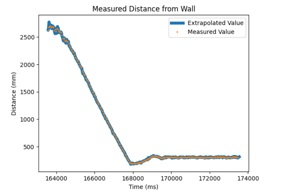
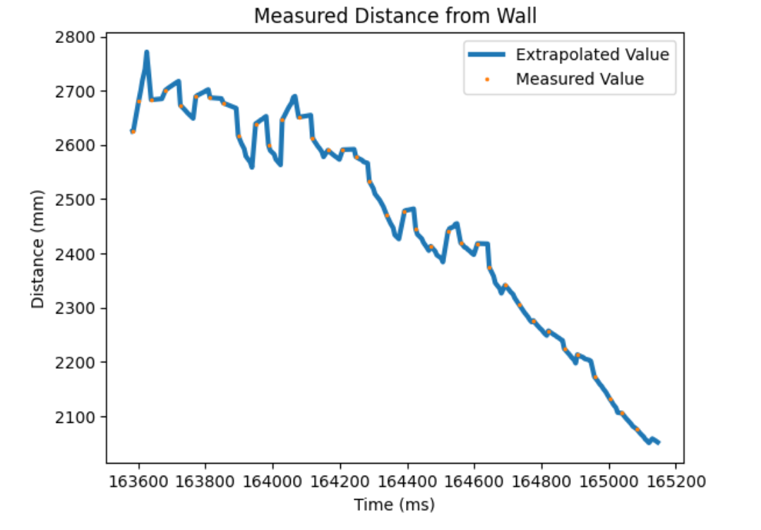
Since the control loop is able to execute much faster than the TOF sensor can record new data, I implemented a simple linear extrapolation algorithm to estimate the robot's distance from the wall in between sensor measurements. This algorithm takes the two previously measured TOF sensor readings and calculates the slope between these two points. Using this slope and the elapsed time since the last sensor reading, the robot estimates its current distance from the wall. This allows the controller to behave more accurately while waiting for new sensor data.
For the above P control test, I recorded when TOF sensor data was ready or not, and plotted the measured and extrapolated distance values below.
To extrapolate data measurements, I implemented two flag variables to check if the TOF sensor had recorded two measurements yet. Since the extrapolation algorithm requires the previous two data points to compute the next expected value, the robot must wait until it has two sensor measurements recorded.
if(!distanceSensor1.checkForDataReady()){
    if(first_time == false && second_time == false){
      PIDPOS_current_distance = last_reading + ((last_reading - previous_reading) / (last_time - previous_time)) * (millis() - last_time);
    }
    else{
      PIDPOS_current_distance = PIDPOS_last_measured_distance;
    }

    PIDPOS_data_ready = 0;
  }
  else{
    PIDPOS_current_distance = distanceSensor1.getDistance();
    PIDPOS_last_measured_distance = PIDPOS_current_distance;
    distanceSensor1.clearInterrupt();
    PIDPOS_data_ready = 1;

    previous_reading = last_reading;
    last_reading = PIDPOS_last_measured_distance;
    previous_time = last_time;
    last_time = PIDPOS_current_time;
    if(first_time){
      first_time = false;
      second_time = true;
    }
    if(second_time){
      second_time = false;
    }
  }
With this test complete, I concluded my position control implementation. While I would've liked to implement integral and derivative terms to my controller, I encountered numerous bugs during this lab that slowed my development abilities. I am looking forward to Lab 6 and will attempt to implement a more sophisticated controller for that lab.
Acknowledgments
I would like to thank all of the TAs and Professor Helbling for their assistance during this lab. From mysterious software bugs, to late night hardware malfunctions, I encountered a lot of roadblocks during this lab and would not have been able to complete it without their help. I also consulted Stephan Wagner's Lab 5 webpage to assist with my understanding of PID controllers.