Table of Contents
This lab focuses on using a PID controller to control the orientation of the robot. Since the robot (for now) is restricted to motion in the X-Y plane, this lab focuses solely on control of the robot's yaw.
The robot will be programmed with a predefined setpoint value, representing the desired yaw angle of the robot's orientation. By using a PID controller, the robot will measure its current orientation and record the error between its current and desired configuration. By turning each side of the robot's wheels in opposite directions, the robot is able to perform an in-place turn.
To calculate the robot's yaw, I used the IMU's gyroscope. The functionality of this sensor is described in detail in Lab 2. By intgerating the output of the robot's gyroscope, one can accurately determine the current yaw of the robot. In Lab 2, I observed that the gyroscope experiences significant drift when left in a stationary position for long periods of time. To account for this, I made use of the robot's Digital Motion Processor (DMP).
Prelab
Much of the debugging work required for this lab was implemented in lab 5. However, as this lab focuses on orientation control rather than position control, I created variants of each debugging command for this lab. The main debugging command I implemented allowed me to send sensor data from the robot to my laptop. On the Artemis, this command sends several arrays to the laptop via bluetooth:
case SEND_PID_YAW_DATA:{
    for(int i = 0; i < TIME_ARRAY_SIZE; i++){
        tx_estring_value.clear();
        tx_estring_value.append(time_stamps[i]);
        tx_estring_value.append("|");
        tx_estring_value.append(yaw_array[i]);
        tx_estring_value.append("|");
        tx_estring_value.append(left_motor_speeds[i]);
        tx_estring_value.append("|");
        tx_estring_value.append(right_motor_speeds[i]);
        tx_estring_value.append("|");
        tx_estring_value.append(KP_ARRAY[i]);
        tx_estring_value.append("|");
        tx_estring_value.append(KI_ARRAY[i]);
        tx_estring_value.append("|");
        tx_estring_value.append(KD_ARRAY[i]);
        tx_estring_value.append("|");
        tx_estring_value.append(DATA_READY_ARRAY[i]);
        tx_characteristic_string.writeValue(tx_estring_value.c_str());
    }
    INDEX = 0;
    break;
}
As well as a function to record relevant sensor data during each iteration of the control loop:
void RECORD_PIDYAW_DATA(
  int C_TIME,
  float C_YAW,
  float C_L_SPEED,
  float C_R_SPEED,
  float C_KP,
  float C_KI,
  float C_KD,
  int DATA_READY
){
  if(INDEX < 2000){
    time_stamps[INDEX] = C_TIME;
    yaw_array[INDEX] = C_YAW;
    left_motor_speeds[INDEX] = C_L_SPEED;
    right_motor_speeds[INDEX] = C_R_SPEED;
    KP_ARRAY[INDEX] = C_KP;
    KI_ARRAY[INDEX] = C_KI;
    KD_ARRAY[INDEX] = C_KD;
    DATA_READY_ARRAY[INDEX] = DATA_READY;
    INDEX += 1;
  }
}
On the Python side, my notification handler is quite similar to the one I developed for lab 5:
def notification_handler(uuid, value):
    global i
    raw_value = ble.bytearray_to_string(value)
    PID_DATA = raw_value.split("|")
    time_list.append(float(PID_DATA[0]))
    yaw_list.append(float(PID_DATA[1]))
    left_motor_list.append(float(PID_DATA[2]))
    right_motor_list.append(float(PID_DATA[3]))
    kp_list.append(float(PID_DATA[4]))
    ki_list.append(float(PID_DATA[5]))
    kd_list.append(float(PID_DATA[6]))
    data_ready_list.append(PID_DATA[7])
Additionally, I implemented commands to set the PID controller constants and setpoint value remotely so that I wouldn't need to recompile code onto the Artemis every time I wanted to make a slight adjustment to the controller. With these debugging steps out of the way, I began implementing the orientation controller.
PID Control - Overview
This lab uses a PID controller to control the orientationg of the robot. A PID Controller takes in sensor data, measures the error between the robot's current and desired configuration, and then adjusts acutator values to move the robot in a direction that will reduce the measured error. Mathematically, the algorithm makes use of the error term and its derivative and integral with respect to time:
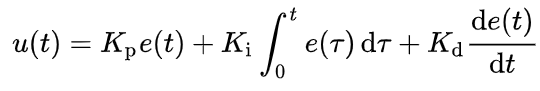
By setting the gain for each term of the controller, one can find an optimal system that controls the orientation of the robot in an accurate and efficient manner. For this lab, the error term is the difference between the desired and measured yaw of the robot.
Digital Motion Processor
Before diving into designing the PID controller, I had to ensure that my sensor's measurements were accurate. As mentioned previously, the gyroscope's readings are prone to a bias/drift error when integrated over long periods of time. Obviously, this would cause major issues for an orientation controller. For example, if the physical robot is stationary for a long period of time, the gyroscope may measure that it is rotating, even though this is not true in reality. To reduce/mitigate this drift effect, I turned to the IMU's Digital Motion Processing Unit.
According to its datasheet, the digital motion processor incorporates the IMU's acclerometer, gyroscope, and compass to maintain optimal performance for recorded sensor data.
The DMP is disabled by default as it requires several kilobytes of memory to operate. I updated the IMU's library files to enable the DMP. The DMP is prone to issues when data is read too slowly. The DMP uses a FIFO stack to record data, and if this isn't read fast enough, it can fill up and cause memory issues. To prevent this issue from occuring, I also added a delay to my control loop to wait for data to be recorded to fill the DMP's queue. I did not slow down the sampling rate of the DMP, but I may adjust this as I dive further into the lab.
Using the provided example code, I adjusted the data recording function to only measure the sensor's yaw value, since this controller does not consider pitch or roll data. Shown below is my function used to record the robot's yaw data. I implemented relevant variables as global variables so that I could access them outside of the scope of the data recording function.
double qw;
double qx;
double qy;
double qz;

double t3;
double t4;
double DMP_YAW;

void measure_DMP_data(){
  icm_20948_DMP_data_t data;
  myICM.readDMPdataFromFIFO(&data);

  if ((myICM.status == ICM_20948_Stat_Ok) || (myICM.status == ICM_20948_Stat_FIFOMoreDataAvail)) // Was valid data available?
  {
    if ((data.header & DMP_header_bitmap_Quat6) > 0) // We have asked for GRV data so we should receive Quat6
    {
      // Scale to +/- 1
      double q1 = ((double)data.Quat6.Data.Q1) / 1073741824.0; // Convert to double. Divide by 2^30
      double q2 = ((double)data.Quat6.Data.Q2) / 1073741824.0; // Convert to double. Divide by 2^30
      double q3 = ((double)data.Quat6.Data.Q3) / 1073741824.0; // Convert to double. Divide by 2^30

      double q0 = sqrt(1.0 - ((q1 * q1) + (q2 * q2) + (q3 * q3)));

      qw = q0;
      qx = q2;
      qy = q1;
      qz = -q3;

      // yaw (z-axis rotation)
      t3 = +2.0 * (qw * qz + qx * qy);
      t4 = +1.0 - 2.0 * (qy * qy + qz * qz);
      DMP_YAW = atan2(t3, t4) * 180.0 / PI;
    }
  }

  if (myICM.status != ICM_20948_Stat_FIFOMoreDataAvail) // If more data is available then we should read it right away - and not delay
  {
    delay(10);
  }
}
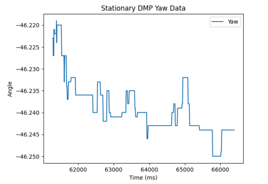
I conducted two tests to ensure that the DMP was operating properly. First, I measured yaw data for five seconds while the robot was stationary. As seen below, the DMP's output was relatively constant, with a mean value value of -46.24 degrees and a standard deviation of 0.008 degrees. Clearly, the DMP eliminates the drift error that is caused by the gyroscope by fusing several sensors together.
I also conducted a test with the robot executing a left turn for five seconds. Shown below is the measured yaw for this test:
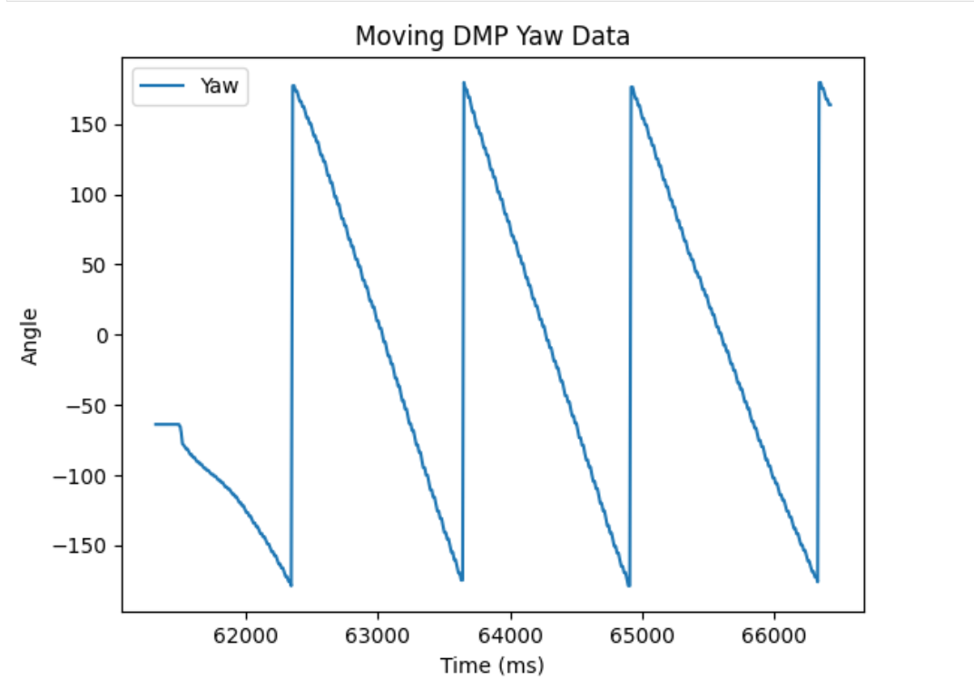
The DMP supports rapid and accurate data collection. As seen in lab 2, the IMU's accelerometer and gyroscope can produce inaccurate and/or noisy results on their own. However, when sensor fusion is implemented, the IMU can produce extremely accurate and precise readings. With the DMP setup complete, I was now able to accurately measure the robot's yaw, and I began designing my PID controller.
PID Controller
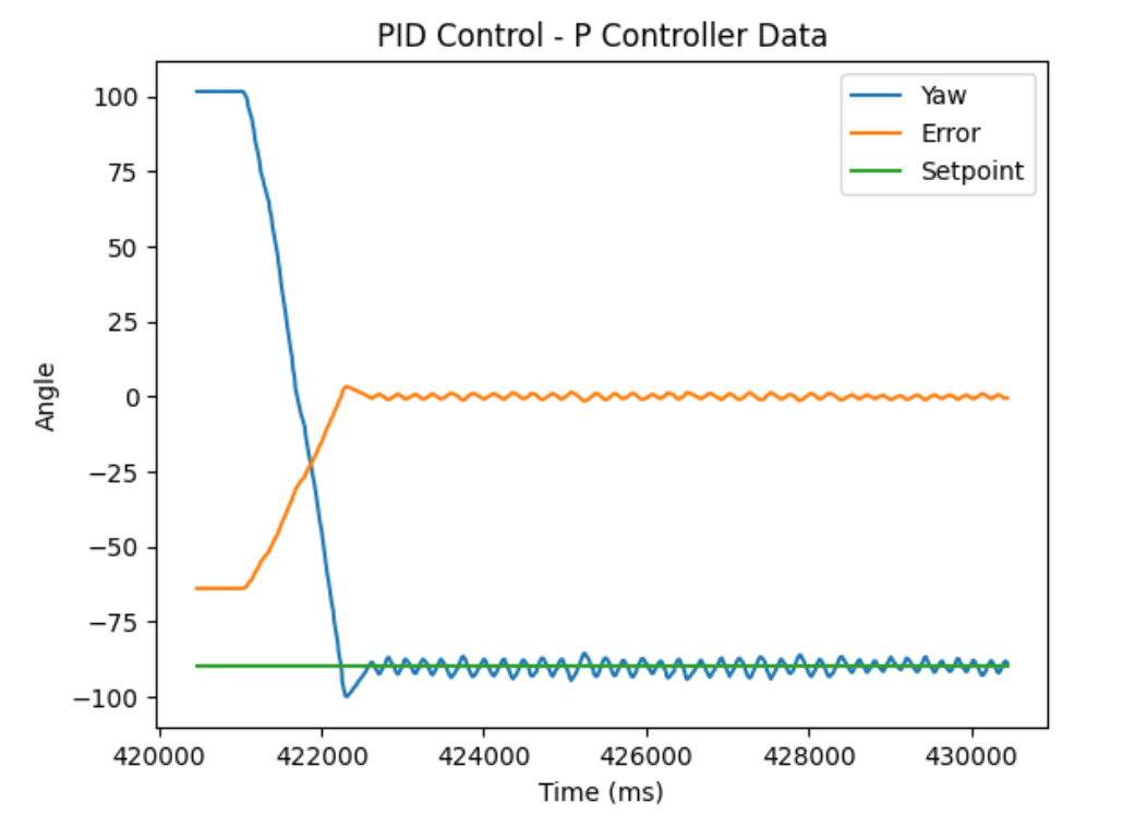
I began by implementing a P controller, using mostly the same code as in Lab 5. However, I adjusted the control loop to read DMP data rather than TOF data.
Initially, I began with a KP constant of 2. This resulted in large oscillations which are not desired in an optimal controller. After numerous adjustments to my motors and controller algorithm, I settled on a KP value of 0.2. This test and its data can be seen below:
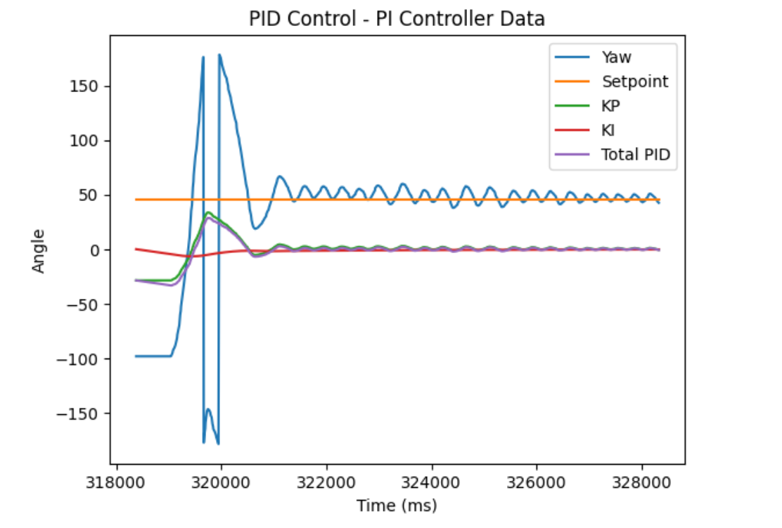
Next, I implemented the integral term to create a PI controller. The integral term considers the robot's error from its setpoint orientation over long periods of time. As more time passes where the robot's error is large, the integral term will grow and have a stronger contribution to the controller's output. Since P controllers are susceptible to steady state error, the integral term works to reduce this effect. One issue that arises with an integral controller is integral windup. If the robot is far away from its setpoint, the integral term can quickly become very large and cause the controller to overshoot its setpoint. To account for this, I limited the integral term's magnitude to be less than 300. This corresponds to a maximum speed of 300% from the integral controller. While this value is still quite large, it places a limit on the controller so that integral term does not spiral out of control.
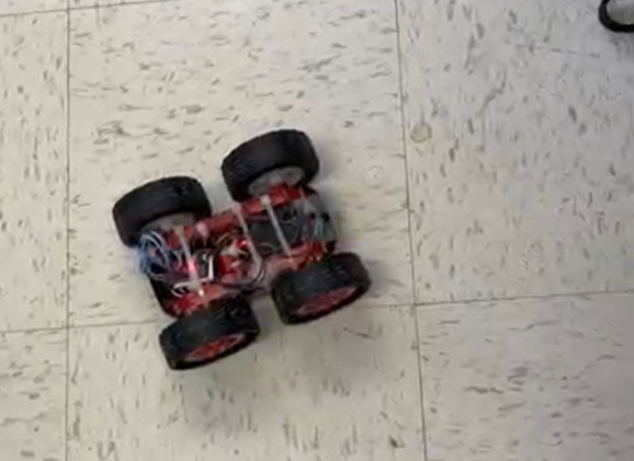
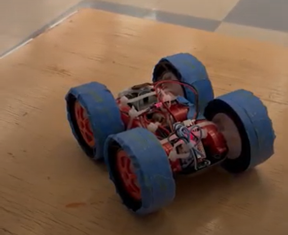
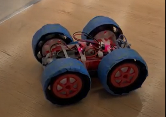
Through rigorous testing and debugging, I was able to implement a successful PI controller with a P value of 0.3 and an I value of 0.05. Shown below is a video of my robot successfully moving its yaw to 45 degrees, as well as the relevant controller and sensor data. A few notable debugging steps were made while adding to my controller. First, I found that my robot required a significantly high PWM input to the motors in order for the robot to overcome friction and actually begin turning. To help reduce this threshold, I added tape to the wheels of my robot. In theory, I had hoped this would allow the robot to turn when supplied with lower PWM values, but in practice, I did not notice a significant difference from the original wheel setup.
Additionally, I experienced quite a bit of frustration while designing my controller, as my robot would often get stuck in a continuous loop of turning rapidly in one direction. After a lot of testing and debugging, I traced the source of this error to several print statements that were present in my control loop for debugging purposes. These print statements in practice were limiting the speed of the control loop to 50 ms, which made the robot incredibly unresponsive to changes in its orientation. After removing these print statements, my controller worked much better.
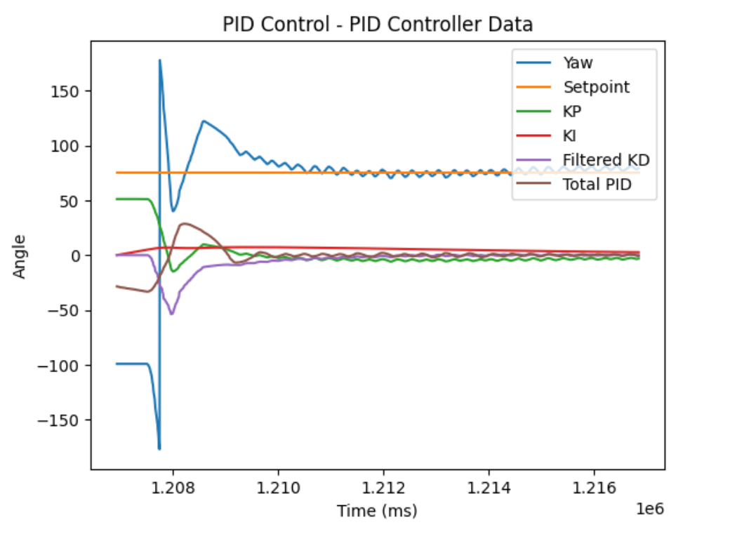
Finally, I implemented a derivative term to my controller. The derivative term reacts to rapid changes in the system's current state. As the error function changes rapidly, the derivative term will become large. The derivative term is also sensitive to noise in the robot's sensors, so I implemented a low pass filter to help adjust for this. I used an alpha value of 0.02 for this filter, which was determined through testing different values and determining which one led to the best performance. My final PID controller had constants of 0.3, 0.1, and 0.15 for KP, KI, and KD respectively.
My final PID control loop code is shown below.
void runPIDOrientationControl(){
  // Record DMP Data
  PIDYAW_KD_LAST_TERM = PIDYAW_KD_FILTER_TERM;
  PIDYAW_LAST_ERROR = PIDYAW_ERROR;
  PIDYAW_LAST_YAW = PIDYAW_CURRENT_YAW;
  PIDYAW_LAST_TIME = PIDYAW_CURRENT_TIME;
  PIDYAW_CURRENT_TIME = millis();
  if(PIDYAW_FIRST_TIME){
    PIDYAW_DT = 0;
    PIDYAW_FIRST_TIME = false;
  }
  else{
    PIDYAW_DT = (PIDYAW_CURRENT_TIME - PIDYAW_LAST_TIME) / 1000;
  }

  measure_DMP_data();
  if(isnan(DMP_YAW)){
    PIDYAW_CURRENT_YAW = PIDYAW_LAST_YAW;
    YAW_DATA_READY = 0;
  }
  else{
    PIDYAW_CURRENT_YAW = DMP_YAW;
    YAW_DATA_READY = 1;
  }

  PIDYAW_ERROR = -1*(PIDYAW_SETPOINT - PIDYAW_CURRENT_YAW);
  PIDYAW_OPP_SETPOINT = PIDYAW_SETPOINT - (PIDYAW_SETPOINT < 0 ? -1 : 1) * 180;
  if(abs(PIDYAW_ERROR) > 180.0){
    PIDYAW_ERROR += (PIDYAW_OPP_SETPOINT - PIDYAW_CURRENT_YAW) / abs(PIDYAW_OPP_SETPOINT - PIDYAW_CURRENT_YAW) * 360;
  }

  // Calculate PID Terms
  PIDYAW_KP_CURRENT_TERM = PIDYAW_KP_CONSTANT * PIDYAW_ERROR;
  PIDYAW_ERROR_INTEGRAL = (PIDYAW_ERROR_INTEGRAL + (PIDYAW_ERROR * PIDYAW_DT));
  if(PIDYAW_ERROR_INTEGRAL > 300){
    PIDYAW_ERROR_INTEGRAL = 300;
  }
  else if(PIDYAW_ERROR_INTEGRAL < -300){
    PIDYAW_ERROR_INTEGRAL = -300;
  }
  PIDYAW_KI_CURRENT_TERM = PIDYAW_KI_CONSTANT * PIDYAW_ERROR_INTEGRAL;

  if(PIDYAW_D_FIRST_TIME == true){
    PIDYAW_KD_CURRENT_TERM = 0;
    PIDYAW_D_FIRST_TIME = false;
  }
  else{
    PIDYAW_KD_CURRENT_TERM = PIDYAW_KD_CONSTANT * (PIDYAW_ERROR - PIDYAW_LAST_ERROR) / PIDYAW_DT;
    PIDYAW_KD_FILTER_TERM = 0.02 * PIDYAW_KD_CURRENT_TERM + 0.98 * PIDYAW_KD_LAST_TERM;
  }

  PIDYAW_TOTAL = PIDYAW_KP_CURRENT_TERM + PIDYAW_KI_CURRENT_TERM + PIDYAW_KD_FILTER_TERM;

  PIDYAW_SPEED = PIDYAW_TOTAL;

  if(abs(PIDYAW_SPEED) > PIDYAW_MAX_SPEED && PIDYAW_MAX_SPEED > 0){
    PIDYAW_SPEED = PIDYAW_MAX_SPEED;
  }
  else if(abs(PIDYAW_SPEED) > PIDYAW_MAX_SPEED && PIDYAW_MAX_SPEED < 0){
    PIDYAW_SPEED = -1 * PIDYAW_MAX_SPEED;
  }
  else if(PIDYAW_SPEED > 0 && PIDYAW_SPEED < 40){
    PIDYAW_SPEED = 40;
  }
  else if(PIDYAW_SPEED < 0 && PIDYAW_SPEED > -40){
    PIDYAW_SPEED = -40;
  }

  // Set Motor Speed
  if(PIDYAW_TOTAL < 0){
    turnLeft(-1*PIDYAW_SPEED);
  }
  else if(PIDYAW_TOTAL > 0){
    turnRight(PIDYAW_SPEED);
  }
  else{
    stop_motors();
  }

  // Log PID Data
  RECORD_PIDYAW_DATA(PIDYAW_CURRENT_TIME, PIDYAW_CURRENT_YAW, current_speed_left, current_speed_right, PIDYAW_KP_CURRENT_TERM, PIDYAW_KI_CURRENT_TERM, PIDYAW_KD_FILTER_TERM, YAW_DATA_READY);
}
The loop begins by recording relevant values from the previous cycle in order to be used for derivative and integral calculations. Next, I record new DMP sensor measurements. If the DMP is not ready to be sampled, I use the Yaw measurement from the previous cycle. Next, I limit my error to be within -180 and 180 degrees to prevent sharp jumps when the yaw measurements cross the -180/180 degree threshold. Next, I calculate the P, I, and D terms for my controller. Lastly, I control the speed, using a minimum PWM percentage of 40% to make sure the wheels are able to turn the robot regardless of the PID controller's output. Lastly, I record data from each loop cycle for debugging purposes.
Conclusion and Acknowledgement
Overall, I learned a lot of PID controllers in this lab. Although I experienced a lot of bugs which slowed my development time significantly, I was able to get a successful PID controller working to control the orientation of my robot. As I work on future labs that require PID control, I will continue to tune the values of my controller. During my work on this lab, I referenced Stephan Wagner's lab 6 webpage for insight into the integral and derivative terms. I also used several online resources such as Wikipedia, the National Instruments PID webpage, and lecture notes from Caltech's CDS 101: Analysis of Feedback Systems course.